

Working with audio in scenes
This section is the practical operator's view of how audio flows from inputs, through layers, into scenes, and out to targets — including the level recommendations that keep your output clean.
Activating audio preview
Enable audio preview by ticking the speaker icon in the Scene view function area above the preview pane:

Composer can mix and process 4 × stereo channels in parallel.
Layer audio
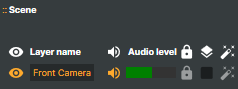
Each layer with audio carries its own speaker icon in the layer list:
Selecting an audio-bearing layer surfaces a dedicated VU meter at the bottom of the layer panel with the layer-level controls:

| Control | Effect |
|---|---|
Volume (dB) |
Adjusts this layer's audio level. |
Pan |
Stereo balance, left ↔ right. |
Channel mapping |
Stereo (default), Left, or Right. |
Scene audio
Each scene has its own VU meter showing the combined audio levels from every layer in that scene, plus a basic processing chain:

| Stage | Effect |
|---|---|
Low cut |
High-pass filter for low-frequency reduction (rumble, mic-stand thumps, HVAC hum). |
Compressor |
Smoothly reduces audio above the threshold. |
Limiter |
Brick-wall ceiling that signals cannot exceed. |
Volume (dB) |
Output trim before the audio reaches any target attached to the scene. |
Audio chain flow
Audio is mapped, processed, and routed through these stages in order:
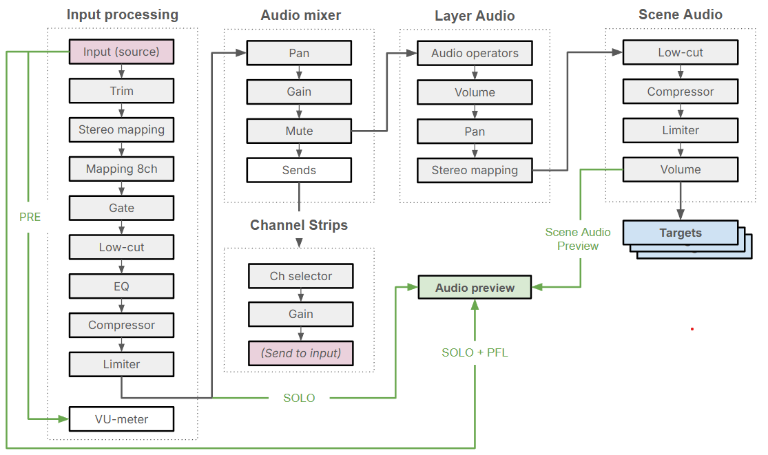
- Input — per-input chain (trim, gate, low-cut, EQ, compressor, limiter).
- Mixer strip — pan, gain, mute, solo, sends.
- Layer audio — per-layer volume / pan / mapping inside the scene.
- Scene audio — combined-layer audio → scene chain → master volume.
- Targets — every target attached to the scene receives the same scene mix.
For per-stage details and the full chain diagram, see Audio processing workflow below; for the per-strip Inspector, see Channel strip inspector.
Audio summing — and why it can clip
All layer audio sources in a scene are added (summed) into a single stereo mix. This is the most common source of unintended clipping: combining two unrelated sources at 100 % peak each results in a 200 % summed peak — well past digital clipping into hard distortion.
Recommendations
- Keep each audio layer at a maximum of −6 dB (≈ 50 %).
- Watch the scene-level stereo meter; the scene total should not exceed 0 dB (100 %).
- Use
Gain,Limiter, orCompressoroperators to bring loud layers down rather than letting them sum hot. - Apply a
Limiteron the scene's output as a safety net — see the Limiter operator and the LIMITER tab on the Channel Strip Inspector. - Watch the target-side scene audio meter for 100 %+ warnings during a show.
Understanding dBFS (decibels relative to full scale)
Composer's audio levels are measured in dBFS — 0 dBFS is the digital ceiling (no signal can be louder), and every value below 0 is a negative number representing how much headroom is left. Levels are also displayed as a percentage of full scale.
| Percentage | dBFS (approx.) |
|---|---|
| 100 % | 0 dBFS |
| 50 % | −6 dBFS |
| 25 % | −12 dBFS |
| 10 % | −20 dBFS |
| 1 % | −40 dBFS |
Why are dB values negative?
0 dBFS is the absolute maximum — exceeding it produces digital clipping. Negative dB values indicate signal levels below the maximum. A −6 dBFS peak means the signal is 6 dB quieter than the digital ceiling and has 6 dB of headroom remaining.
Example
If two layers each peak at −6 dBFS (≈ 50 %) and their summed result peaks at 0 dBFS (100 %), there's no headroom left for any other layer or for any subsequent processing. Pull each contributing layer down by another 3 dB and the same combination peaks at −3 dBFS, leaving safe margin.
RDP / remote-desktop note
If you're operating Composer over RDP, ensure RDP audio forwarding is configured for the client and that the project is running at a 48 kHz sample rate. Mismatches force resampling and can cause clicks or short dropouts on the forwarded audio.
Tip
Use the Audio tab in Settings to adjust how long the signal-overload indicator stays active, and Project Options to change the maximum peak level displayed in all audio meters.