

Channel strip inspector
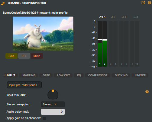
The Channel Strip Inspector is a panel on the right side of the Audio mixer. When you click on a mixer strip the Inspector updates to show that strip's controls and audio configuration.
Note
By default, Composer processes audio in stereo. The VU meters in the Inspector are only displayed if Composer has been set to process 8-channel audio in Project Options.
Collapse / expand
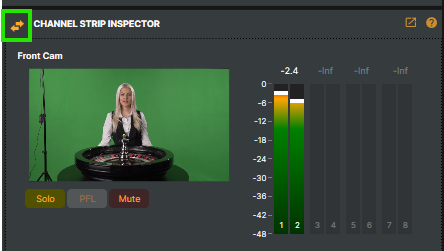
The Inspector can be collapsed to save screen space. Click the double-arrow icon in the top-left corner to collapse it — the Inspector then appears as a vertical bar on the right side of the audio mixer. Click the icon again to expand and access the full controls.

Extract to a separate window
Tip — Extract to a separate window
The Channel Strip Inspector can be extracted into its own standalone window. The floating window remains visible regardless of where you navigate within Composer, giving direct access to the selected channel strip's audio options at all times.

What you can do
From the Channel Strip Inspector, you can:
- Perform advanced audio routing, such as sending audio to other channel strips or auxiliary buses.
- Reroute audio to different stereo pairs using channel mapping.
- Toggle Solo, Mute, and PFL, mirroring the controls on the strip and the input itself.
- Apply audio processing — gating, equalisation, compression, sidechain ducking, and limiting.
- Access detailed audio options without leaving the mixer view.
Header controls
The top section of the Inspector displays:
- Input Name — the name of the selected audio input.
- Preview Thumbnail — a visual preview of the video source, or a waveform icon for audio-only inputs.
- VU Meters — real-time audio level meters (8-channel display when enabled in Project Options).
- Solo — isolates this input's audio, muting all other inputs.
- PFL (Pre-Fader Listen) — monitors the audio signal before the fader is applied. Only available when Solo is active.
- Mute — silences the input's audio output.
Configuration tabs
Eight tabs cover the per-strip configuration in detail.
INPUT
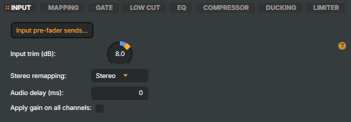
Basic input settings for gain, stereo handling, routing, and timing adjustments.
| Parameter | Description | Range | Default |
|---|---|---|---|
Input pre-fader sends… |
Button that opens the Input Routing Configuration window to send audio to other channel strips before the main fader. Not available for Scenes and Virtual Audio strips. | Button | — |
Input trim (dB) |
Adjusts the gain level of the input signal across all audio channels (pre-fader). | −24 to +24 dB | 0 dB |
Stereo remapping |
Channel reassignment for the stereo output. (Legacy) = no remapping; Stereo = standard stereo; Left mono = output left channel to both speakers; Right mono = output right channel to both speakers. | Dropdown | Stereo |
Audio delay (ms) |
Adds a delay to the audio signal (pre-fader). Useful for synchronising audio with video or compensating for processing latency. | 0 to 5000 ms | 0 ms |
Apply gain on all channels |
When enabled, adjustments to the channel strip's gain slider (fader) are applied to all audio channels simultaneously. | On / Off | Off |
Input pre-fader sends
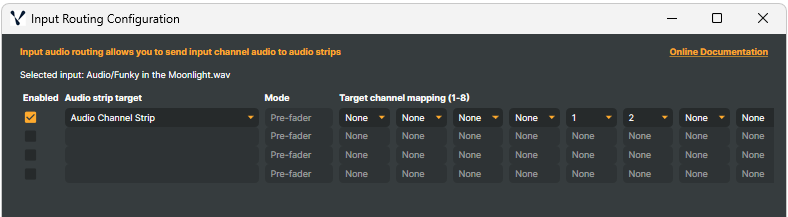
The Input pre-fader sends… button opens the Input Routing Configuration window, which lets you send the input's audio signal to other channel strips (such as auxiliary buses) before the main fader is applied.
Note
This feature is not available for Scenes and Virtual Audio strips. The "Input pre-fader sends…" button is disabled for those input types.
Important — Pre-fader routing
Audio sent via pre-fader sends is routed before the main fader of the sending strip — adjusting the sending strip's main fader will NOT affect the level of audio being sent to the target strip. The send level remains constant regardless of the sending fader position.
However, on the receiving strip, the main fader always controls channels 1 & 2. So if you route pre-fader audio to channels 1 & 2 on the receiving strip, that strip's fader CAN adjust the volume. If you route to channels 3-8, the receiving strip's fader will NOT affect those channels unless "Apply gain on all channels" is enabled on the receiving strip.
This makes pre-fader sends ideal for creating independent monitor mixes or effects sends that shouldn't be affected by the main mix levels.
Input Routing Configuration features:
- Enable / Disable Sends — check or uncheck to activate individual send configurations.
- Audio Strip Target — select which channel strip will receive the audio (e.g. auxiliary bus, submix).
- Mode — currently only Pre-fader sends are available.
- Target Channel Mapping (1-8) — map each of the 8 source audio channels to specific destination channels on the target strip. Options: None, 1, 2, 3, 4, 5, 6, 7, 8. Set channels to "None" to exclude them from the send.
This is useful for monitor mixes, effects sends, or parallel processing chains where you need the audio signal before any fader adjustments are applied.
MAPPING
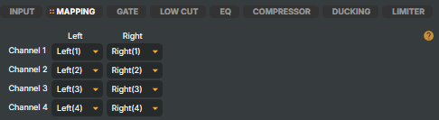
Provides fine-grained channel remapping. Each of the four stereo channel pairs can be explicitly assigned to either the left or right output.
| Parameter | Description | Default |
|---|---|---|
Channel 1 - Left |
Assigns Channel 1 left audio to output. Options: (Mute), Left(1), Right(1), Left(2), Right(2), Left(3), Right(3), Left(4), Right(4). | Left(1) |
Channel 1 - Right |
Assigns Channel 1 right audio to output. Same options. | Right(1) |
Channel 2 - Left |
Assigns Channel 2 left audio to output. | Left(2) |
Channel 2 - Right |
Assigns Channel 2 right audio to output. | Right(2) |
Channel 3 - Left |
Assigns Channel 3 left audio to output. | Left(3) |
Channel 3 - Right |
Assigns Channel 3 right audio to output. | Right(3) |
Channel 4 - Left |
Assigns Channel 4 left audio to output. | Left(4) |
Channel 4 - Right |
Assigns Channel 4 right audio to output. | Right(4) |
GATE
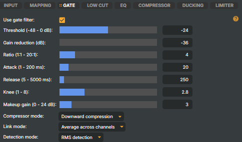
A noise gate attenuates audio that falls below a level you set, so quiet background sound is pushed down (or silenced) while the signal you actually want passes through untouched. It watches the incoming level: while the signal sits above the Threshold the gate is open and audio passes at full level; when it drops below, the gate closes and applies the Gain reduction you've dialled in. The Attack and Release times control how quickly it opens and closes, so speech still sounds natural rather than chopped.
The gate earns its keep on live microphones that pick up room tone between phrases — a podium mic in a noisy hall, a guest lav near an air-conditioning vent, or a panel where several open mics bleed into one another. Set the threshold just above the noise floor so quiet speech still opens the gate while the silence between sentences stays clean: too high and you clip the start of soft words, too low and the noise never gets removed. Leave it bypassed on clean, controlled sources where there is nothing to gate.
| Parameter | Description | Range | Default |
|---|---|---|---|
Use gate filter |
Activates or deactivates the gate. | On / Off | Off |
Threshold (dB) |
The level below which the gate begins to reduce the signal. | −48 to 0 dB | −24 dB |
Gain reduction (dB) |
The amount of attenuation applied when the gate is closed. | −36 to 0 dB | −36 dB |
Ratio |
How aggressively the gate attenuates signals below the threshold. Higher values create a harder gate effect. | 1:1 to 20:1 | 4:1 |
Attack (ms) |
How quickly the gate opens when the signal exceeds the threshold. | 1 to 200 ms | 20 ms |
Release (ms) |
How quickly the gate closes after the signal falls below the threshold. | 5 to 5000 ms | 250 ms |
Knee |
Transition smoothness around the threshold. Higher values create a softer, more gradual gating effect. | 1 to 8 | 2.8 |
Makeup gain (dB) |
Adds gain after the gate processing to compensate for any level reduction. | 0 to 24 dB | 0 dB |
Compressor mode |
Downward compression reduces volume above threshold; Upward compression raises volume below threshold. | Dropdown | Downward compression |
Link mode |
Average across channels averages signal levels across channels; Max across channels uses the highest signal level. | Dropdown | Average across channels |
Detection mode |
RMS detection responds to average signal energy; Peak detection responds to signal peaks. | Dropdown | RMS detection |
LOW CUT
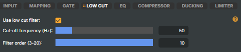
A high-pass (low-cut) filter that progressively rolls off everything below a chosen cutoff frequency while leaving the rest of the signal intact. Low-frequency energy you don't hear as pitch — mic-stand thumps, footstep rumble, wind, HVAC hum, plosive "pops" on close mics — still eats headroom and muddies the mix, and the low-cut strips it out before it reaches the rest of the chain.
For speech, a cutoff around 80–100 Hz cleans up rumble without thinning the voice; raise it cautiously on very deep voices only if rumble persists, and lower it on full-range music so you don't lose legitimate bass. The Filter order sets how steeply the level drops just below the cutoff — higher orders cut more sharply. It's gentle enough to leave enabled on most spoken-word sources.
| Parameter | Description | Range | Default |
|---|---|---|---|
Use low cut filter |
Activates or deactivates the low-cut filter. | On / Off | Off |
Cut-off frequency (Hz) |
The frequency below which audio is attenuated. | 20 to 200 Hz | 50 Hz |
Filter order |
Steepness of the filter slope. Higher values create a sharper cutoff. | 3 to 20 | 10 |
EQ
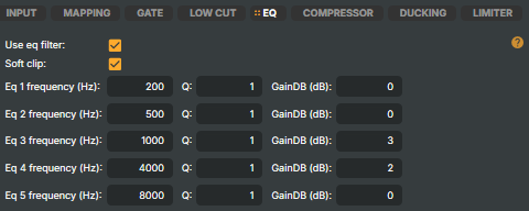
A five-band parametric equaliser for shaping tone — correcting a dull or boomy source, carving out a problem frequency, or adding presence and "air" to a voice. Each of the five bands is a bell filter with three controls: a centre Frequency, a Q that sets how wide a range around that frequency is affected, and a Gain that boosts or cuts it. Because the bands overlap, you can combine them to build almost any tonal curve.
Cuts are usually safer than boosts: a narrow cut (high Q) is ideal for surgically removing a specific resonance or harshness, while a wide, gentle boost (low Q) adds character without sounding processed. Typical broadcast-voice moves are a small dip around 200–400 Hz to clear "boxiness", a slight lift around 2–4 kHz for intelligibility, and a gentle lift above 8 kHz for air. Soft clip guards against harsh digital distortion when you push boosts hard, and is best left on for live use.
| Parameter | Description | Default |
|---|---|---|
Use eq filter |
Activates or deactivates the equaliser. | Off |
Soft clip |
Enables soft clipping to prevent harsh digital distortion when boosting frequencies. | On |
EQ bands
Each of the 5 EQ bands provides three adjustable parameters:
| Band | Frequency (Hz) | Q | Gain (dB) |
|---|---|---|---|
EQ 1 |
200 | 1.0 | 0 |
EQ 2 |
500 | 1.0 | 0 |
EQ 3 |
1000 | 1.0 | 0 |
EQ 4 |
4000 | 1.0 | 0 |
EQ 5 |
8000 | 1.0 | 0 |
Parameter descriptions:
- Frequency (Hz) — the centre frequency for the EQ band.
- Q — bandwidth (quality factor). Lower values affect a wider frequency range; higher values are more precise.
- Gain (dB) — the amount of boost or cut applied at the centre frequency.
COMPRESSOR
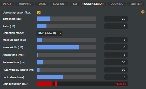
A dynamic-range compressor narrows the gap between the loudest and quietest parts of a signal, so a source that swings from a whisper to a shout sits at a steadier, more controlled level in the mix. Once the signal crosses the Threshold, the compressor reduces everything above it by the Ratio you set; Attack and Release govern how quickly it clamps down and lets go, and Makeup gain brings the now-tamer signal back up to a useful level. The Gain reduction meter shows how hard it is working in real time.
It's the workhorse of broadcast-voice processing — a presenter who leans in and pulls back, a guest who mumbles then laughs loudly, or a board feed with inconsistent levels all benefit. A moderate ratio (around 3:1–4:1) taking just a few dB off the peaks is transparent and natural; high ratios with a fast attack tip over into obvious "pumping", which is occasionally a deliberate effect but usually best avoided on speech. Watch the meter and aim for gentle, occasional reduction rather than constant heavy squashing.
| Parameter | Description | Range | Default |
|---|---|---|---|
Use compressor filter |
Activates or deactivates the compressor. | On / Off | Off |
Threshold (dB) |
The level above which compression begins. | −48 to +36 dB | −12 dB |
Ratio |
The amount of compression applied. A 4:1 ratio means a signal 4 dB above threshold is reduced to 1 dB above. | 1:1 to 20:1 | 4:1 |
Detection mode |
RMS (default) reacts to average energy (Root Mean Square) over a time window — natural and smooth, best for vocals, buses, and mastering. Peak reacts to the instantaneous maximum amplitude — fast and aggressive, best for limiting or drums. | Dropdown | RMS (default) |
Makeup gain (dB) |
Adds gain after compression to restore overall level. | 0 to 36 dB | 3 dB |
Knee width (dB) |
Transition smoothness around the threshold. Wider knees provide a gentler compression onset. | 1 to 8 dB | 6 dB |
Attack time (ms) |
How quickly the compressor responds to signals exceeding the threshold. | 1 to 200 ms | 5 ms |
Release time (ms) |
How quickly the compressor stops reducing gain after the signal falls below the threshold. | 1 to 500 ms | 50 ms |
RMS window length (ms) |
The time window used for RMS level detection. Longer windows provide a smoother response. | 1 to 500 ms | 30 ms |
Look ahead (ms) |
Allows the compressor to anticipate peaks for more transparent compression. | 1 to 10 ms | 5 ms |
Gain reduction (dB) |
A meter displaying the current amount of gain reduction being applied. | Display only | — |
DUCKING
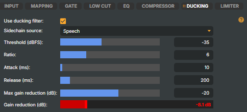
A sidechain ducking compressor that automatically lowers this input's level whenever a chosen trigger (sidechain) input is loud enough. The classic use is dipping background music under a voice-over, or ambient room sound under a commentator — every time the trigger input speaks, this input gets quieter on its own, and recovers when the trigger pauses. Ducking runs after the compressor and before the limiter in the signal chain.
| Parameter | Description | Range | Default |
|---|---|---|---|
Use ducking filter |
Activates or deactivates sidechain ducking. | On / Off | Off |
Sidechain source |
The input whose audio level triggers ducking on this input. Lists every audio-capable input except this one, plus None to disable. Pick the voice/commentary mic when you want this input to dip under speech. The selection is remembered with the project. | Dropdown | None |
Threshold (dBFS) |
The sidechain level at which ducking starts engaging. Lower (more negative) values trigger ducking more easily; higher values only react to clearly loud passages. | −60 to 0 dBFS | −30 dBFS |
Ratio |
How aggressively this input is dipped once the threshold is crossed. 1:1 means no ducking; 4:1 gives a typical music-under-speech feel; 10:1+ produces a very obvious dip. | 1:1 to 20:1 | 4:1 |
Attack (ms) |
How quickly this input dips once the trigger crosses threshold. Short attacks duck instantly; longer attacks produce a softer "fade-down". | 1 to 500 ms | 10 ms |
Release (ms) |
How quickly this input comes back up after the trigger goes quiet. Longer releases keep the input down across natural pauses. | 10 to 2000 ms | 200 ms |
Max gain reduction (dB) |
A hard floor on how much the input can be dipped. −20 dB keeps the input clearly under the trigger but still audible; −30 dB or more makes it almost disappear. | −48 to 0 dB | −20 dB |
Gain reduction (dB) |
A meter displaying the current amount of gain reduction being applied by ducking. | Display only | — |
LIMITER
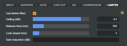
A brick-wall limiter sets an absolute ceiling the output can never exceed, no matter how loud the incoming signal gets. Where a compressor gently reduces level above a threshold, a limiter is the hard backstop: it uses a short Look ahead to catch peaks before they arrive and clamps them to the Ceiling, preventing the digital clipping that causes audible crackle and protecting downstream encoders, transmitters, and listeners' equipment.
It belongs at the very end of the chain as a safety net — after gating, EQ, compression, and ducking have done their work. Set the ceiling a touch below 0 dBFS (the −0.1 dB default is typical) to leave headroom for downstream encoding, and pick a release time that recovers smoothly without pumping. Used purely as protection it should rarely engage; if the gain-reduction meter is active all the time, lower your levels upstream rather than leaning on the limiter to do the leveling.
| Parameter | Description | Range | Default |
|---|---|---|---|
Use limiter filter |
Activates or deactivates the limiter. | On / Off | Off |
Ceiling (dB) |
The absolute maximum output level. Signals attempting to exceed this are clamped. | −36 to +6 dB | −0.1 dB |
Release time (ms) |
How fast the limiter recovers gain after a peak. Lower values produce louder output but may introduce distortion. | 5 to 500 ms | 100 ms |
Look ahead (ms) |
Allows the limiter to anticipate peaks for transparent limiting. Essential for brick-wall limiting. | 1 to 8 ms | 2 ms |
Gain reduction (dB) |
A meter displaying the current amount of gain reduction being applied. | Display only | — |
VU meters
By default, Composer processes audio in stereo. When configured to process 8 channels in Project Options, the Channel Strip Inspector displays an 8-channel VU meter showing individual levels for all channels.
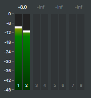
In stereo (the default), the strip header's level meters provide all the metering you need.
Reset settings
Tip — Reset settings
Right-click on any tab to access a context menu with the option to reset settings to their default values. Useful for quickly returning to a known starting point when experimenting with audio processing.
Audio processing workflow
For more on the internal audio-processing pipeline and signal-chain order, see Audio processing workflow above.