

Wheel Tracker
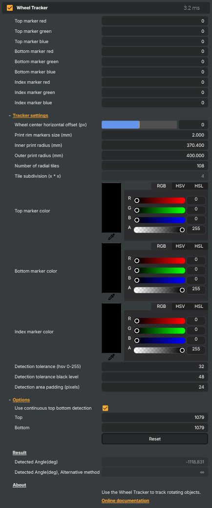
The Wheel Tracker is a generic, marker-based rotation tracker — point it at a spinning wheel that's been printed with a small set of coloured markers around the rim, and it reports back the rotation angle every frame. Pair it with the Wheel Visualizer (or any custom downstream operator that reads Detected Angle) to overlay graphics — numbers, segment highlights, sponsor logos, animated pointers — that stay locked to the wheel as it spins.
Where the Roulette Wheel Tracker V2 is purpose-built for casino roulette wheels (full 3D mesh, per-pocket positions, TAF reference files), the Wheel Tracker is the simpler, marker-driven option for any other rotating object: prize wheels on game shows, fortune wheels, custom branded spinners, mechanical dials, or studio props built for a single show. As long as you can paint a few markers on the rim, the tracker can find them.
How tracking works
The operator looks for three printed markers on the wheel's rim:
- A Top marker at the 12-o'clock reference position (a known colour, e.g. cyan).
- A Bottom marker at the 6-o'clock reference position (a different known colour).
- A short binary index pattern — a row of small dots or dashes encoding a rotation index — that lets the tracker distinguish a half-turn from a full turn.
Frame by frame, the tracker scans the configured detection area for pixels matching each marker colour (within an HSV tolerance), reconstructs the wheel centre and orientation from the marker positions, then reads the binary pattern to resolve which rotation index the wheel is currently in. The result is exposed as a single Detected Angle (deg) value — and a second alternative-method angle for diagnostics when the primary detection is uncertain.
Because everything runs on the GPU and the matching is pixel-local (no large reference image, no per-frame texture comparison), the operator stays cheap enough for HD and UHD broadcasts without measurable latency.
What you need on the wheel
A successful capture starts with how the wheel is built, not with the operator settings. You need:
- A clear contrast between the rim and the marker colours — the markers are detected by colour, so they need to stand out from the rim background and from each other. Saturated, distinct hues (cyan / yellow / magenta is a common combination) read best on broadcast cameras.
- Both markers visible in every frame — if either marker is hidden by a hand, ball, or shadow for long stretches, the tracker will report
Detected Angleas∞(no result) until both markers reappear. - A small binary index pattern spanning a known number of radial tiles around the rim, distinct in colour from the two markers.
What you control
The property panel groups settings by purpose:
- Marker colours —
Top marker color,Bottom marker color,Index marker color. Use the colour pickers (or eyedropper) on a paused frame of the live feed to sample the exact rendered colour of each printed marker. - Tracker settings — physical dimensions used to reconstruct the wheel geometry:
Wheel center horizontal offset (px),Print rim markers size (mm),Inner / outer print radius (mm),Number of radial tiles, andTile subdivision. - Options —
Use continuous top bottom detectionandTop/BottomY-pixel hints, used to constrain the search area along the vertical axis (helps with crowded scenes where the markers' rough vertical position is known). - Detection tolerances —
Detection tolerance (hsv 0–255)for colour matching,Detection tolerance black levelfor the binary pattern, andDetection area padding (pixels)for the search-region margin. - Result — read-only outputs:
Detected Angle (deg)(the primary result, also exposed to the Script Engine) andDetected Angle (deg), Alternative method(a second-opinion calculation useful for diagnostics).
When the markers are well-defined and the colours sample cleanly, most of these defaults work as-is — the only field you typically tune per project is the marker colours themselves.
Pairing with a visualizer
The tracker reports an angle but doesn't draw anything. To put a graphic on screen:
- Wheel Visualizer is the matching follower — drop it on a layer downstream, point it at a folder of per-segment textures, and it renders an overlay rotated to match the tracker's reported angle every frame.
- Custom workflows can read
DetectedAnglefrom the Script Engine and drive any other operator (a positional graphic, a video layer rotation, an external connector call) off it.
Example use cases
- TV prize wheels and game shows — overlay segment names, prizes, or live odds on top of a real spinning wheel.
- Promotional spinners — sponsor logos that follow each segment of a branded prize wheel around the rim.
- Studio props — mechanical dials, compasses, or instrument readouts where an overlay graphic needs to follow the prop's rotation.
- Sports broadcast spinners — wheel-of-fortune-style game elements on live shows where each segment needs its own graphic.
Licensing
The Wheel Tracker requires the Wheel Tracker plug-in licence. Without it the operator still loads — but only runs for up to 2 hours per Composer session. Once that budget is exceeded the operator auto-bypasses (its IsActive flips to false and the layer falls through unchanged), and a single warning is written both to the global Composer log and to the operator's Log panel.
The same 2-hour budget applies under a Composer Core licence regardless of plug-in licensing — Core projects can run the tracker for up to 2 hours per session for evaluation, then it auto-bypasses.
Restart Composer to reset the budget for another evaluation session. Production deployments should run on a Subscription or Full licence with the Wheel Tracker plug-in enabled.
Practical tips
- Pick distinct, saturated marker colours. The top and bottom markers need to be unambiguously different from each other, from the rim background, and from any branding artwork that might bleed into the rim. Cyan-yellow-magenta is a common, robust combination.
- Sample the colours on the live feed, not on the design file. Camera white balance, lighting, and codec colour rendering all shift the markers' on-screen RGB. Use the eyedropper on a paused live frame, not the print artwork's source colour.
- Watch
Detected Angle (deg), Alternative method. If the alternative regularly disagrees with the primary by more than a couple of degrees, marker detection is borderline — widenDetection toleranceslightly or improve lighting. - Use the
Logpanel during commissioning. Confidence/visibility warnings surface there first; a clean log with no warnings is the target state before going live. - Restart for trial extension. During licensing evaluation, restart Composer to reset the 2-hour budget. For real productions, get a Subscription or Full licence with the Wheel Tracker plug-in.
Wheel Tracker - Settings
Tracker settings
Tracker settings — physical wheel layout, marker colours, and detection tolerances.
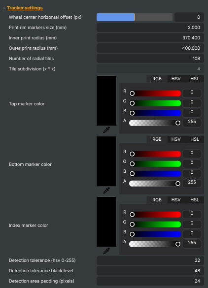
| Property | Description |
|---|---|
Wheel center horizontal offset (px) |
Horizontal offset of the wheel centre from the frame centre, in pixels. [min=-200, max=200, default=0]. Use this when the wheel is not perfectly centred horizontally in the camera view. Adjust until the detection cross sits over the real wheel hub. |
Print rim markers size (mm) |
Width of the white rim band around the printed marker pattern, in millimetres. [min=1, max=20, default=2]. Must match the physical printed pattern on the wheel — used to locate the boundary between the coloured top/bottom markers and the binary tile area. |
Inner print radius (mm) |
Inner radius of the printed pattern on the wheel, in millimetres. [min=100, max=2000, default=370.4]. Measured from the wheel centre to the inside edge of the pattern. Required for correct tile placement. |
Outer print radius (mm) |
Outer radius of the printed pattern on the wheel, in millimetres. [min=100, max=2000, default=400]. Measured from the wheel centre to the outside edge of the pattern. The difference between outer and inner radius defines the height of the marker band. |
Number of radial tiles |
Number of radial tiles around the wheel. [min=32, max=512, default=108]. Must match the physical printed pattern. Each tile encodes a position around the wheel. |
Tile subdivision (x * x) |
Subdivision factor used inside each tile (x * x cells). [min=3, max=8, default=4]. Must match the printed binary pattern on the wheel. |
Top marker color |
Reference colour of the top marker on the printed pattern. Pick a colour that closely matches the printed marker under stage lighting; raise Detection tolerance (hsv 0-255) if the marker is not detected, lower it if there are false detections from similar background colours. |
Bottom marker color |
Reference colour of the bottom marker on the printed pattern. Pick the colour as it appears on camera. The top and bottom markers together define the vertical extent of the wheel pattern and the per-pixel scale. |
Index marker color |
Reference colour of the index marker that anchors the binary pattern. The index marker is searched for in each frame and used as the starting point for reading the binary tiles. |
Detection tolerance (hsv 0-255) |
Colour-match tolerance when locating coloured markers, on a 0-255 scale. [min=0, max=128, default=32]. Raise if markers are missed under varying lighting; lower if other parts of the image are wrongly detected as markers. |
Detection tolerance black level |
Threshold below which a tile cell is read as a black bit. [min=16, max=128, default=48]. Raise if dark tiles are misread as bright; lower if bright tiles are misread as dark. |
Detection area padding (pixels) |
Extra padding around the detection area, in pixels. [min=0, max=48, default=24]. Increase to give the index-marker search a larger area when the wheel jitters; decrease for tighter detection and slightly faster processing. |
Options
Options — top/bottom marker behaviour.
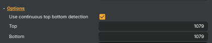
| Property | Description |
|---|---|
Use continuous top bottom detection |
When enabled, the top and bottom markers are re-detected every frame. Turn on for a moving camera or wheel that may shift in frame; turn off (after the wheel is found) to lock the detection area and gain a small amount of processing headroom. |
Invert angle |
When enabled, negates the computed wheel angle. [default=false]. Use when the wheel rotates in the opposite direction from what your visualizer expects. Applies to both WheelAngleDeg and WheelAngleDeg2. |
Top |
|
Bottom |
|
Reset |
Reset all settings to their defaults (geometry, marker colours, detection tolerances, debug opacities). |
Result
Result — the live tracker output read by visualizers and scripts.

| Property | Description |
|---|---|
Detected Angle(deg) |
Currently detected wheel rotation angle, in degrees. Updates every frame. Useful from scripts for triggering on specific positions, or as the input to follow-on visualizer operators that overlay graphics tied to the wheel. |
Detected Angle(deg), Alternative method |
Alternative-method detected wheel angle, in degrees. Updates every frame. Computed from the index marker plus a sub-tile interpolation; useful as a comparison value to WheelAngleDeg when calibrating. |
Rotation speed (deg/frame) |
|
Stopped threshold (frames) |
Number of consecutive frames at the same detected angle before the wheel is reported as stopped. [min=3, max=50, default=25]. Lower values declare a stop sooner but risk false positives when the wheel slows briefly; higher values are more conservative. |
Wheel is stopped |
True when the wheel has shown no rotation for StoppedWheelFrameCountThreshold consecutive frames (read-only). Use from a script to trigger close-up cuts, reveal graphics, or log the result when the wheel settles. |
Log
Log — recent component messages and warnings.
| Property | Description |
|---|---|
ComponentLog |
Inherits from: AbstractOperator, AbstractAudioMetering.
See also: Wheel Tracker in Script Engine Objects.